Aluminum Glazing Extrusions
System Overview
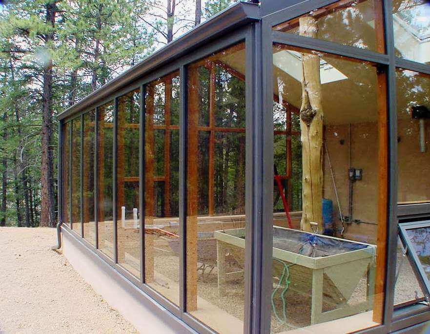
An aluminum glazing system is made of specific extrusions for glass or any solid transparent sheathing such as multi-wall polycarbonate panels, lexan, Plexiglas, or acrylic sheets
Durable Design
Linear Clamp System
Versatile Compatibility
Need Help Deciding?
If you are unsure about building with an aluminum glazing system, contact Ralph for details and expert guidance on your project
Glazing Application Categories
Vertical Applications
- Wall glazing systems
- 45° miter corner joints
- Perimeter assembly top & bottom
Sloped Applications
- Roof glazing systems
- Bevel cap at bottom perimeter
- Same base bar assembly
Assembly Selection Guide
Three Essential Profile Types
- Perimeter Assembly
- Available in 3 heights
- 1 inch, 5/8 inch, 1/4 inch
- Uses flat cap design
- 2 13/16 inches wide
- Mullion Assembly
- Accepts all 3 thicknesses
- 3 1/8 inches wide
- Same cap as Perimeter
- Joins between posts
- Purlin Assembly
- For roof applications
- Sits horizontally on purlins
- Uses bevel cap
- Divides glazing rows
EDPM Glazing Rubber
Structural Requirements
Important Note
3 Inch Surface
Suitable Support Structures
Wood Construction
- Glue-lam beams
- 3 by 6 to 3 by 8 rafters
- 3 by 3 posts
- Double 2 by framing
- Laminated rafters and posts
Other Materials
- Steel rectangular tubes
- Sized to meet local snow loads
- Sized to meet local wind loads
Wood Protection Recommendation
Exposed wood beams should be stained and sealed with two coats of sealer. This keeps the wood long lasting and protects it from UV damage.
Installation Guidelines
Pre-Drilling Requirements
Base Bars (7/32" bit):
Cap Bars (9/32" bit):
Weep Holes & Setting Blocks
Weep Holes (3/16" bit):
Setting Blocks:
Glazing Size Specifications
Pre-Drilling Requirements
- Measure center to center of base screw track
- Glazing must rest flat on EDPM rubber
Best Practice
Measure from: Outer edge of EDPM rubber
Side to side: Full bay width
Height: Setting block to top rubber edge
Installation Procedures
Start with Top Perimeter Bars
Use a string line from end to end. Ensure bar is even and equally distant from top corners. Caulk back side where needed. Miter top corners at 45°.
Install Side Base Bars
Make sure sides are square with frame and top Perimeter bar. Miter top corners and caulk the splice.
Install Vertical Mullion Bars
Place onto rafters. Butt top of each Mullion to inside top of Perimeter bar. Align bottom with lower Perimeter bar.
Install Purlin Base Bars
Fill screw holes with clear silicone. Position between Mullion bars with notched ends overlapping Mullion gutter edge by 1/8" to 1/4".
Flashing & Leak Prevention
Flashing is Required
Flashing must be used with any aluminum glazing system. Flashing at the top, bottom, and sides is project specific and recommended for a leak proof installation.
Bottom Flashing
Run sill flashing continuously under bottom Perimeter base bar and vertical Mullion. Overlap 4-6" with silicone caulk.
Top Flashing
Run continuous flashing over top Perimeter cap, crease downward. Ridge cap covers top bar flashing for double layer protection.
Side Flashing
Clamp continuous flashing between Perimeter base bar and cap. Bend to rake at outer edge of rafter or structure end.
Professional Installation Benefits
Waterproof
Long Lasting
Long Lasting
Waterproof